Cat 6 Poe Camera Wiring Diagram : 27 Poe Camera Wiring Diagram - Wire Diagram Source Information
Cat 6 Poe Camera Wiring Diagram : 27 Poe Camera Wiring Diagram - Wire Diagram Source Information. I need to install new sockets but don't know the wiring diagram. Poe outdoor cam rj45 cable pinouts. Post by melvin » mon oct 23, 2017 9:17 am. It reveals the parts of the circuit as simplified shapes, and the power as well as signal connections between the gadgets. You may buy ethernet cable like the one in the link below.
ads/bitcoin1.txt
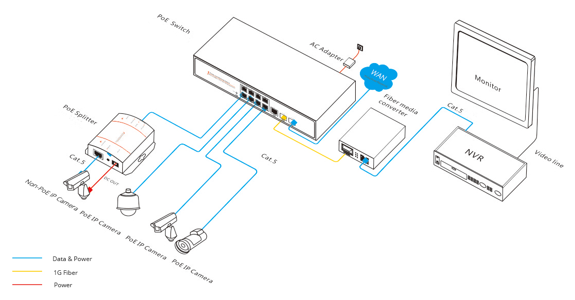
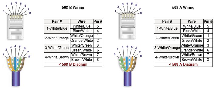
Currently, 2 types of wiring are widely used for ip security cameras which are cat6 or cat5e twisted pair cabling. As external power doesn't needed in poe ip cameras, therefore connect only the cameras through poe via cat5 / cat 6 cables. A circuitry layout is a straightforward graph of the physical connections and also physical layout of an electric system or. Brown & white pin 8: Pins 1 and 6 are power, pin 1 is negative and pin 6 is positive.
Ip Camera Cat6 Wiring Diagram from www.fiber-optic-tutorial.com Post by melvin » mon oct 23, 2017 9:17 am. To connect a new connector (rj45 jack) to the hikvision ip camera refer to the diagrams below. Collection of poe camera wiring diagram. The 100' distance is based on the resisitance of the wire. With the discovery of wireless networks which were. The 32 channel admiral pro has the ability to support 32 ip cameras, but only has 16 poe ports on the back. Corrosion of rj45 connector and the camera wires, color matching of swann 815cam camera wires to the cat 5 wire colors with. Pins 1 and 6 are power, pin 1 is negative and pin 6 is positive.
Hikvision ip camera rj45 pin out wiring diagram page 1 power over ethernet poe pinout dahua guide cat 5 cctv full line sno way rj 45 connecter broke need color megapixel cameras and software to a nvr switch faqs lorex cat5 87 gmc tbi network dome installation manual 2nd generation intercom home systems of connect blog intercoms doorbell promotion s2000.
ads/bitcoin2.txt
Hikvision ip camera rj45 pin out wiring diagram page 1 power over ethernet poe pinout dahua guide cat 5 cctv full line sno way rj 45 connecter broke need color megapixel cameras and software to a nvr switch faqs lorex cat5 87 gmc tbi network dome installation manual 2nd generation intercom home systems of connect blog intercoms doorbell promotion s2000. Power is forced into devices. The camera uses one pair to talk to the nvr wire #1 and #2. Currently, 2 types of wiring are widely used for ip security cameras which are cat6 or cat5e twisted pair cabling. Green & white pin 4: A circuitry layout is a straightforward graph of the physical connections and also physical layout of an electric system or. I have two lorex ip cameras (model # mcnb3143) with damaged cat5e sockets. Each component ought to be placed and connected with different parts in particular way. 06:58 2 comments one cannot imagine living without networks in the present times. To get a better idea, the ethernet ip security camera wiring diagram is shown below. A wiring diagram is a simplified standard photographic depiction of an electrical circuit. Pins 1 and 6 are power, pin 1 is negative and pin 6 is positive. When i cut of the female sockets i discovered that there were only six cat5e wires instead of the four twisted pairs.
Water corrode and damage my connection, had to replace with female cat 6 jack. Can you send me the diagram? It consists of directions and diagrams for different varieties of wiring strategies as well as other products like lights, windows, and so on. Poe outdoor cam rj45 cable pinouts. Ip needs 2 pairs of wire to communicate with the nvr.
BG_5120 Images Of Cat5 Poe Wiring Diagram Wire Diagram ... from static-resources.imageservice.cloud Each part should be placed and connected with different parts in specific way. This is what worked for me. 06:58 2 comments one cannot imagine living without networks in the present times. A circuitry layout is a straightforward graph of the physical connections and also physical layout of an electric system or. Wed oct 14, 2015 2:20 pm. Ip needs 2 pairs of wire to communicate with the nvr. Currently, 2 types of wiring are widely used for ip security cameras which are cat6 or cat5e twisted pair cabling. This diagram features 16 cameras connected directly to the admiral nvr.
The splitter is the silver and black box in the middle between the wiring junction box (left) and the access point (right).
ads/bitcoin2.txt
A third option is a fiber to ethernet media converter and a fibre optic cable, which i would recommend across a car park as it will also eliminate lighting strikes coming up the cat5 cable and destroying other equipment. Poe camera wires to cat 5/6 connector (t568b) for these camera models. Ip needs 2 pairs of wire to communicate with the nvr. To get a better idea, the ethernet ip security camera wiring diagram is shown below. Each part should be placed and connected with different parts in specific way. A very common question regarding security cameras and installs is the type of cabling to use. It reveals the parts of the circuit as simplified shapes, and the power as well as signal connections between the gadgets. But sometimes vendors doesn't mention that spec. 06:58 2 comments one cannot imagine living without networks in the present times. I need to install new sockets but don't know the wiring diagram. Pins 2 and 3 transmit data to and from the camera. To connect a new connector (rj45 jack) to the hikvision ip camera refer to the diagrams below. This misconception is surprisingly common, however it is important to remember that power ratings quoted by manufacturers are upper limits and are not fixed.
Otherwise, the arrangement will not function as it should be. 06:58 2 comments one cannot imagine living without networks in the present times. A wiring diagram is a simplified standard photographic depiction of an electrical circuit. Poe outdoor cam rj45 cable pinouts. Power is forced into devices.
How to Make a Category 5 / Cat 5E Patch Cable from www.lanshack.com This misconception is surprisingly common, however it is important to remember that power ratings quoted by manufacturers are upper limits and are not fixed. It consists of directions and diagrams for different varieties of wiring strategies as well as other products like lights, windows, and so on. A third option is a fiber to ethernet media converter and a fibre optic cable, which i would recommend across a car park as it will also eliminate lighting strikes coming up the cat5 cable and destroying other equipment. You may buy ethernet cable like the one in the link below. The six wires on the camera are orange, yellow, green, purple, gray, blue, and brown. Poe camera wires to cat 5/6 connector (t568b) for these camera models. Truly, we have been realized that poe cat5 wiring diagram is being just about the most popular field right now. Poe outdoor cam rj45 cable pinouts.
Water corrode and damage my connection, had to replace with female cat 6 jack.
ads/bitcoin2.txt
I need to install new sockets but don't know the wiring diagram. Corrosion of rj45 connector and the camera wires, color matching of swann 815cam camera wires to the cat 5 wire colors with. Hikvision ip camera rj45 pin out wiring diagram page 1 power over ethernet poe pinout dahua guide cat 5 cctv full line sno way rj 45 connecter broke need color megapixel cameras and software to a nvr switch faqs lorex cat5 87 gmc tbi network dome installation manual 2nd generation intercom home systems of connect blog intercoms doorbell promotion s2000. This misconception is surprisingly common, however it is important to remember that power ratings quoted by manufacturers are upper limits and are not fixed. Pins 2 and 3 transmit data to and from the camera. Wed oct 14, 2015 2:20 pm. You may follow the wire order below to arrange the wires of your rj45 connector. So we attempted to uncover some good poe cat5 wiring diagram graphic to suit your needs. **please do not use this diagram to create a pinout for a separate power source for the simplified poe cameras. And the last option is to use a rf solution. Otherwise, the arrangement won't function as it ought to be. Orange & white pin 2: The 32 channel admiral pro has the ability to support 32 ip cameras, but only has 16 poe ports on the back.
ads/bitcoin3.txt
ads/bitcoin4.txt
ads/bitcoin5.txt
0 Response to "Cat 6 Poe Camera Wiring Diagram : 27 Poe Camera Wiring Diagram - Wire Diagram Source Information"


0 Response to "Cat 6 Poe Camera Wiring Diagram : 27 Poe Camera Wiring Diagram - Wire Diagram Source Information"
Post a Comment